
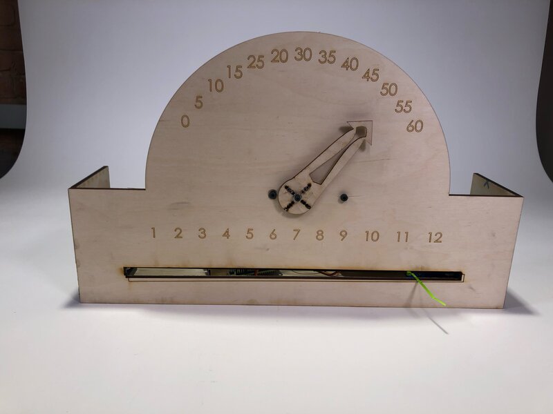
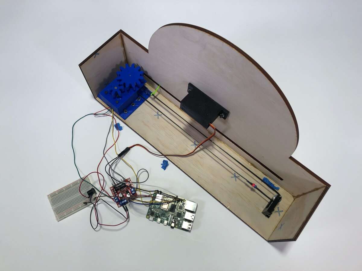
In Robotics at Tufts, I made an electromechanical clock. My 3-person team decided to build a linear clock, which would display the hours along a straight line and the minutes on an arc. Our design consisted of a lasercut wooden frame, a servo motor to actuate the minutes hand, a stepper motor to move the belt-driven hours hand, a gear system, and a Raspberry Pi to control everything.
With just one week total to complete the project, we moved on a very accelerated timeline. We started off by 3D modelling the entire design. My groupmates modelled the clock face, the motor mounts and the indicators, while I focused on the belt drive system. Once we had a model of our design, I got to work on the electronics and code. To run the belt drive, I used the L298N motor driver with a NEMA 17 stepper motor. This allowed me to individually control magnets in the motor and accurately control its position.
An initial test of the gear system.
I wired up the Raspberry Pi to the motor driver and wrote a Stepper motor class in Python to store the position of the motor and simplify control. Early in the project timeline, I tested this code on the gears (designed by my teammate) to verify that I could accurately control the position of the motor.
Next, I wrote a main control script. This code pulls the current time, maps the time to an appropriate output state, and uses my Stepper class to actuate the motors to the necessary locations. In order to map motor outputs to the correct hand locations, I created a dictionary which characterized the PWM pulse (or number of steps) the motor should be at for each numeric value on the clock face — 1 hour or 5 minute increments, respectively. For time values that were not explicitely mapped in the dictionary, I wrote a linear approximation for the location of the hands.
With the software finished, it was time to integrate with the hardware. My teammates and I tensioned the belt system to avoid slipping, attached the motors to the clock structure, and added the indicators. After some testing, the clock was complete!
A sped-up view of the clock operating
This project was integral in teaching me how to design for manufacturability, write control software from scratch, and integrate structures, electronics, and software. Because this entire project was completed in under a week, it forced us to iterate quickly and be considerate in our design decisions. Overall, the project was a lot of fun and I'd love to expand on this idea in a future project.